The Signal Jammer Module is essentially a Power Amplifier. For a Signal Jammer, it is as critical as the motherboard in a computer—it’s the core of the core. When your company aims to create a sophisticated, efficient, and market-successful Signal Jammer product, choosing the right signal jammer modules is essential. It will significantly impact the product’s appearance, performance, and cost.
Typical Appearance of Signal Jammer Module
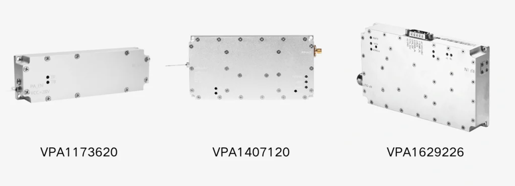
Aluminum Enclosure
These modules look quite similar, don’t they? Yes, that’s because 90% of the appearance elements of these modules are made of aluminum enclosures. Using aluminum alloy for the module housing is a standard choice, as it both protects the circuit board and ensures effective heat dissipation. Previously, we customized copper housings for some clients to achieve superior heat dissipation performance, but this significantly increased both the weight and cost. This is due to the different thermal properties of copper and aluminum. Choosing copper or aluminum ultimately depends on your projected results for the Signal Jammer project. From experience, for power amplifiers under 150W, aluminum housings are generally sufficient for heat dissipation needs.
Slikscreen on the Cover
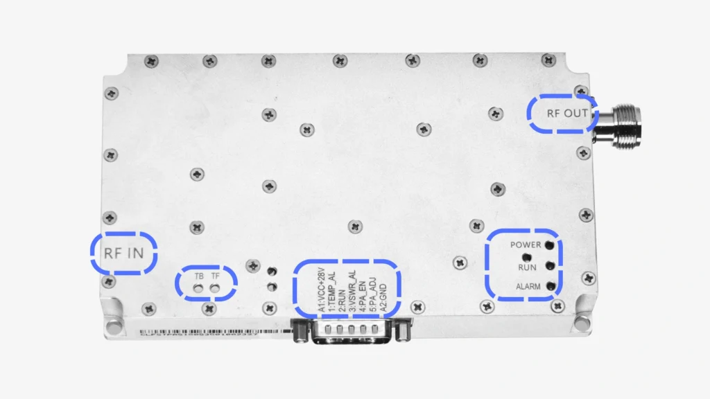
Silkscreen is a type of labeling used to indicate the function of specific areas on the module. Below are common silkscreen markings and their meanings:
VCC+28V: Indicates the positive terminal of the DC 28V power supply.
PA_EN: Enable switch of the RF module by controlling the VCO and transistor switches on the circuit board via a DC 5V current.
RF_IN: RF signal input port. This port is present only when the module does not include an internal signal source and is used to connect an external signal source.
RF_OUT: RF signal output port.
TB/TF: Potentiometer port used to adjust the frequency spectrum. This is generally only used during the manufacturing modulation phase and is not recommended for customer use.
VSWR: Standing wave protection alert. This silkscreen is typically associated with a red LED indicator. When the light is on, it means there is poor contact between the antenna and module.
The silkscreen markings may not be identical on every module. If you’re unsure about a particular marking, feel free to ask your sales contact for clarification.
RF Output Connector
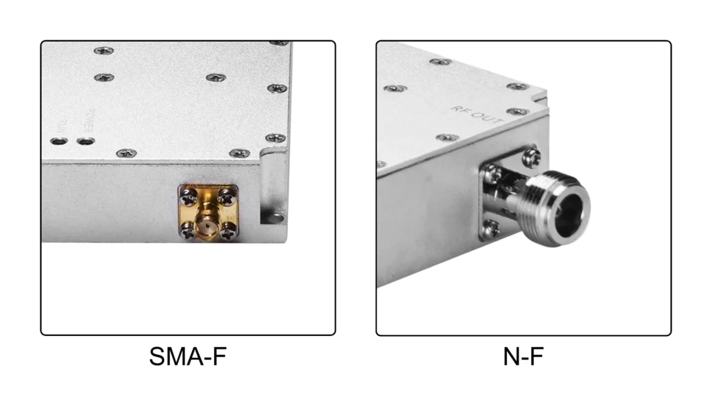
The connector is female. When the module power is ≤50W, SMA connectors are usually used. For modules with power >50W, N connectors are typically used.
Power Supply Connector
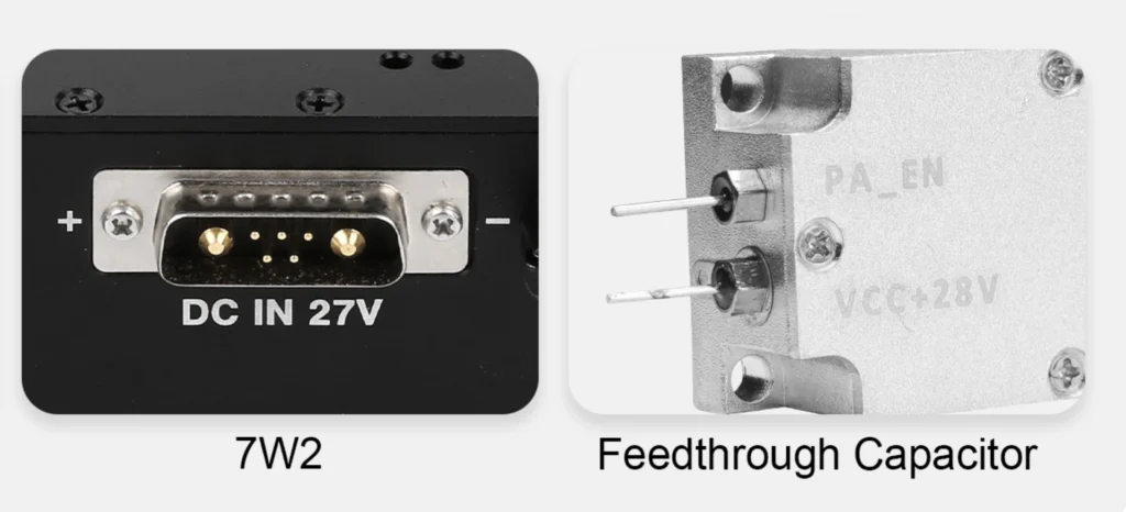
In Zorelock-manufactured modules, we commonly use through-hole capacitors or 7W2 connectors for DC 28V and 5V enable switch power supply. Before shipping, we can, upon your request, solder the power supply wires onto the through-hole capacitors to speed up your assembly process after receiving the module.
In addition to the above typical external features, Zorelock also offers a special DDS RF module DPA15512560, which has a unique structure. It features a black anodized aluminum surface, built-in fan, and heat dissipation fins. The entire module weighs over 1.5 kg. This structure is designed for quick plug-and-play during use, such as in the Portable Signal Jammer Chariot-CM product.
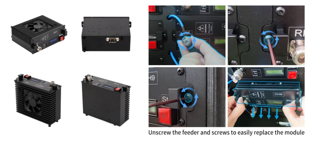
Typical Internal Components of Signal Jammer Module
EMI Shielding Bar
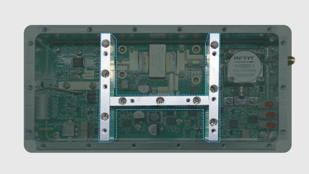
This part, made of aluminum alloy, is often found in high-frequency modules produced by Zorelock. It divides the module into different regions, effectively reducing electromagnetic interference (EMI) from high-frequency signals to other power components, thus improving the module’s electromagnetic compatibility.
Printed Circuit Board (PCB)
The PCB is the foundation of everything. Zorelock exclusively uses Rogers materials for its PCBs, not FR4. While FR4 is commonly used in electronic devices, it is not suitable for high-frequency, high-temperature RF circuit applications. Rogers materials, though more expensive, offer better impedance control, lower signal loss, and superior thermal management. For us, there is no alternative to Rogers PCB.
Voltage-Controlled Oscillator (VCO)
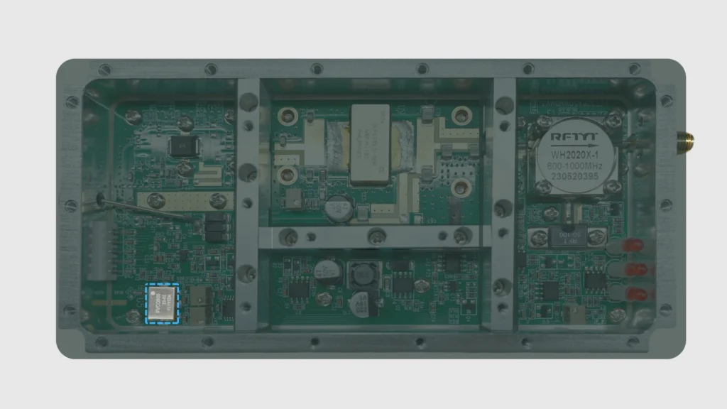
A VCO is a commonly used signal generator. It outputs an analog signal by sweeping frequencies, which is then amplified by the amplifier transistor on the PCB and eventually transmitted by the antenna to form interference signals. Our VCOs have a default signal power of 0dBm, with a maximum bandwidth of around 400MHz (depending on the specific frequency).
Transistor as an Amplifier
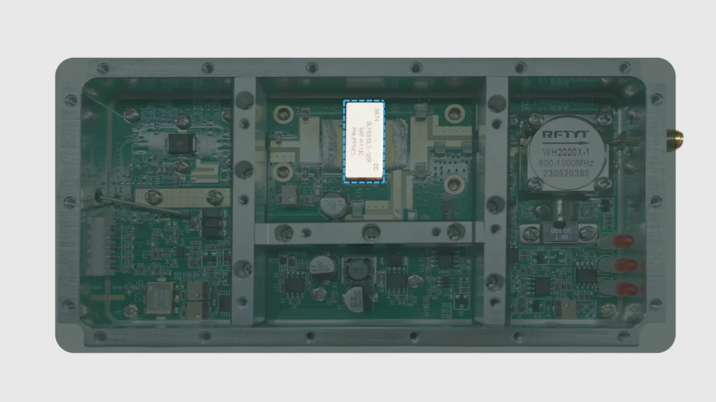
Depending on the gain power, a module may contain multiple transistors of different levels. Transistors are the core components of power amplifiers. The entire PCB is designed around the transistor. In products with frequencies ranging from 20M~4GHz, we commonly use LDMOS (Laterally Diffused Metal-Oxide Semiconductor) transistors. With advances in GaN technology and decreasing costs, we are continuously launching new products using GaN transistors. Compared to LDMOS, GaN modules generate smaller currents, produce less heat, and offer higher efficiency. If you’re unsure about the transistor model used in the module you purchased, feel free to ask your sales contact.
Circulator/Isolator
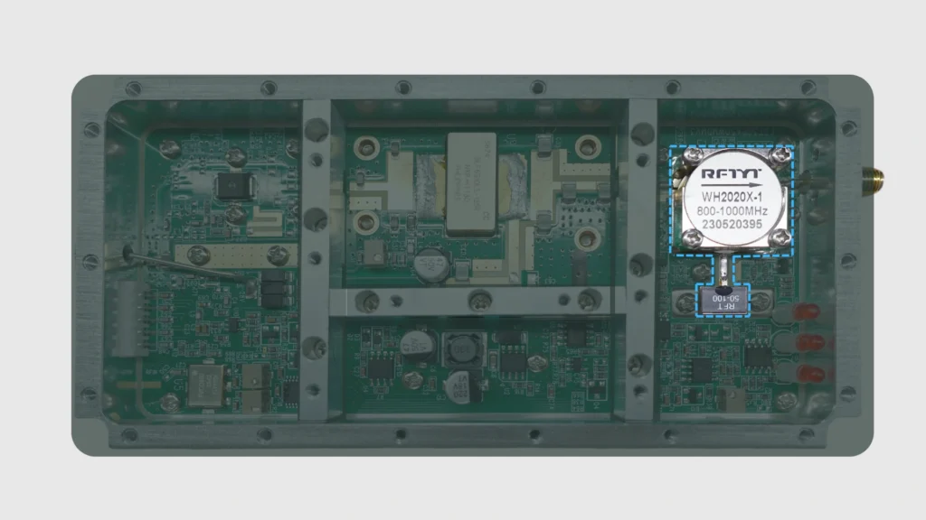
The structures and functions of circulators and isolators are similar. They help reduce the impact of reflected signals on the circuit. For instance, if we forget to install an antenna or install the wrong frequency band antenna, the circulator and isolator will protect the module from damage caused by standing wave reflections.
Other Functional Circuits
In addition to the key components mentioned above, the PCB includes areas dedicated to power supply and status monitoring functions, such as temperature monitoring, power monitoring, and high-temperature protection. These functions are not present in all products and depend on the specific product model.
Application Examples of RF Amplifier Modules in Different Jammer Products
Stationary Drone Jammer Forger-CM Case:
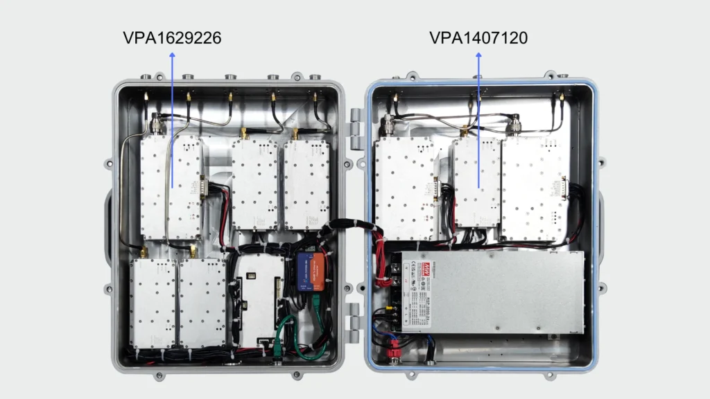
This is a typical 8-channel Forger-CM. Such devices are often deployed in fixed locations for extended periods. Therefore, we installed the 50W RF Amplifier VPA1407120 and RF Amplifier VPA1629226. These modules are connected to a control box via an XH2.54 interface. The control box outputs data to a network module via an RS485 standard, which then transmits the data through an RJ45 interface (Ethernet) to the control terminal. This way, users can check the internal module status on their computer, including power, temperature, and VSWR status, without frequently opening the device for inspection.
Portable Drone Jammer Traveler-CM Case:
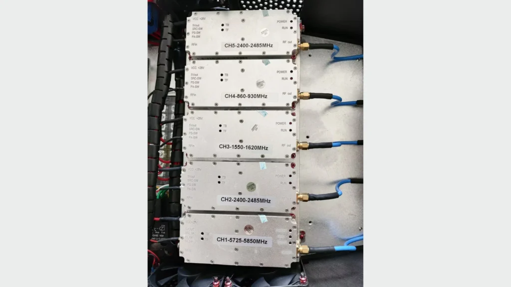
This is a typical 5-channel Traveler-CM. These devices are usually carried by personnel and need to be compact and easy to operate. Therefore, we use smaller modules. In these modules, we eliminate the status monitoring circuits and only use the Enable Switch to turn the module on or off, allowing for a smaller size, lower weight, and reduced cost.
Purchasing Process for Power Amplifier Modules
The purchasing process for RF modules is relatively complex and includes the following stages:
1. Communication Phase
2. Production Preparation Phase
3. Production Phase
4. Packing Phase
5. After-sales
For more details, please refer to our other article, Signal Jammer Module Manufacturing Process: From Order to Delivery
Conclusion: Carefully Consider Multiple Factors When Purchasing Signal Jammer Module
The jammer module is so important that when choosing where to purchase it, you need to consider factors like cost, heat dissipation, interference range, and status monitoring. Therefore, contacting RF module manufacturers like Zorelock is the best choice. Not only does this mean lower prices than intermediaries, but more importantly, you can directly collaborate with your product design team to create an efficient supply chain.

